3D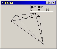
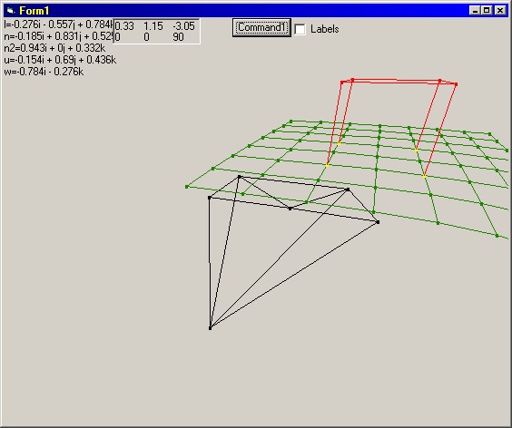
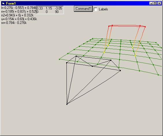
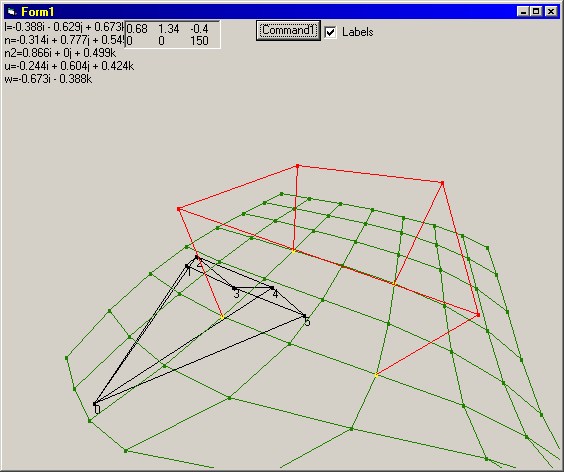
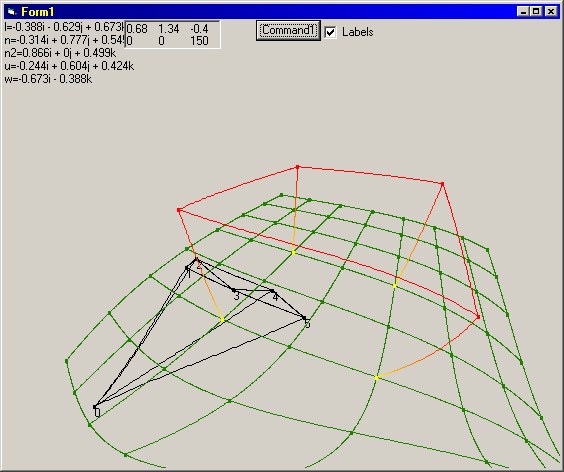
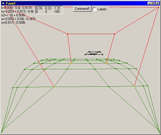
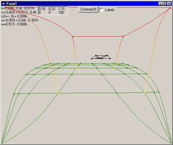
[Full Screenshot] [Full Screenshot] [Full Screenshot] [Full Screenshot] [Full Screenshot] [Full Screenshot] [Sourcecode] [Executable] DescriptionThis program displays a wire-frame 3D world, using trigonometry to work out where each point should be displayed on the screen. I'm going to show the maths behind it underneath, I don't know if this is the quickest way of doing it, but it works, although there are some strange skewing effects at the edges of large objects, due to the way the program works. It is a simple world, with an Elite style 'Viper' space ship that moves continually away from a table, sitting on a plane. These objects are held in complicated data structures, as you can see in the source code. Why I did itI had always wondered how 3d engines worked. When I finally thought of how it could be done, I jumped at the opportunity to put that idea into practice. Other infoEntities and verticesI structured the 3d world by having a number of 'entities' each of which have a position and an array of particles. Each particle contains a list of all the other particles it is connected to, a colour and a position. With this, it is possible to define simple wireframes. I thought that making a fairly solid and practical system for storing the shapes themselves would make drawing them and manipulating them easier.CurvesIt occured to me as I wrote the program, that using my method would require curves to be drawn. If you consider standing on a pair of train tracks, going off into the distance on a flat plain, then the lines appear straight, but two straight lines like this would have to cross whereas the train tracks continue forever, getting closer and closer together until they almost lie alongside each other. This seems to be more like a pair of asymtotic curves, but the lines appear straight. I came to the conclusion that the lines do appear curved, but because of the way that we 'perceive' what we see, our brain straightens them out so they are consistent with how we know a train track's shape to be. If this is true, then all the 3d engines that I have seen before must do the same. This made sense, as it is much quicker to draw a straight line on the screen than a curved line, and speed is of great importance in a 3d engine. I never worked out quite how they were straightened, but I found a modification for Quake that rendered the image in all 6 directions, and then transformed these 6 images into a fishbowl style image. This multiplied the time it took to render each frame by more than 6 times, as there was also a speed cost in the manipulation of the image. The maths behind itThe ideas behind this engine came from a Further Maths lesson. We were just finishing the 3-Dimensional vectors area of the syllabus and I suddenly realised that if you have a person, and a point, then the angle between the point and a vertical plane going through the person, and along the line that they are looking, is the quantity that defines how far left or right the point should be plotted along the screen. Hopefully this diagram will explain that a bit better (click for enlargement): 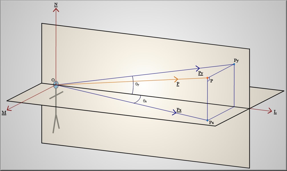
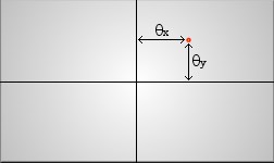 (P is a free floating point in 3d space.)
From that you can use a combination of 3d and 2d techniques to find the two angles given the position vector P and the unit vectors L, N and M That is how _my_ program works. I don't know if this is the method used by graphics cards and software 3d engines. Certainly there is the line straightening to add on top of this code before it will look like other renderers. There is also a speed issue. Whether that is because my vector algorithms are bloated, or I'm using the wrong method, or whether it's just Visual Basic adding overheads, I don't know; but frames are drawn at about 2/3 a second max. Bearable in this case but not much use for anything else. I'm going to have to write this in a faster language, like C, at some point to see what is at fault. |